
Recipe for Reliability - Part 1: NEBS testing and CompactPCI-based equipment design
Table of Contents
• Genesis and purpose of NEBS
• NEBS Level 3 criteria
• NEBS documentation
• Understanding NEBS requirements for physical protection
• Fire resistance and containment
• Earthquakes and vibration
• Contaminants – trouble in the air
• Understanding NEBS requirements for electromagnetic compatibility
• Electrostatic discharge
• Electromagnetic interference
• Jolts from the blue – lightning and AC power faults
There are two important points to remember about NEBS. The first point is that there is no single "best" way to build a NEBS-compliant system. This is because NEBS does not provide design specifications per se. Rather, NEBS is a collection of recommendations and criteria that impact the design of systems. When you design a system or system component for NEBS compliance, you do not design to a strict NEBS blueprint; instead, you design to meet specific NEBS requirements for physical protection, electro-mechanical compatibility, electrical safety and so on. In practice, NEBS is like a roadmap in that it clearly shows you the destination, but leaves how you get there largely up to you. This allows designers considerable flexibility in making their own choices, for better or worse.
The first choices a designer typically makes when building a computing system revolve around the system's hardware platform, or architecture. This article, in part, examines why embedded computing systems based on the inherently rugged, standards-based CompactPCI architecture are much more likely to meet NEBS criteria faster and more completely than systems based on less robust, "industrial" PC architectures.
The second point to bear in mind is that there is an enormous difference between stating that a product is "NEBS-compliant" and being able to say that it has successfully undergone NEBS testing. Telecom OEMs need to ensure that the system components they embed in their Central Office solutions are truly NEBS-compliant. By integrating major components such as embedded systems that have already passed NEBS testing, OEMs can put themselves ahead of the game.
Return to Table of Contents
Genesis and purpose of NEBS
NEBS had its genesis in the 1970s when Bell Labs began producing guidelines for equipment designers to help them focus on physical protection, electromagnetic compatibility and safety, and overall reliability. While originally intended for Central Office equipment, NEBS criteria are of value when designing any kind of mission-critical electronic system, no matter where it will be deployed.
NEBS is now administered by Telcordia, the direct corporate descendent of Bell Labs and Bellcore (Bell Communications Research). Today, in the vast majority of cases, telephone companies will not deploy network equipment until it has been tested to the NEBS criteria. Key NEBS categories include:
- Fire resistance — including ignition resistance and fire containment
- Earthquake and vibration — including the ability to survive a major earthquake as well other vibrations from construction, demolition, transport, etc.
- Electromagnetic compatibility — including the ability to survive lightning strikes and power surges
- Thermal robustness — including the ability to work properly in environments exhibiting extreme temperature and humidity
- Airborne contaminants — including airborne pollutants, corrosives and hygroscopic dust
NEBS testing can be accomplished through a network of independent test laboratories located throughout North America. Achieving NEBS compliance is a complex process and proving this compliance through rigorous testing can be costly. For this reason, many vendors often wait until they have a guaranteed customer for a product before committing themselves to the expense of NEBS testing. However, when testing is performed early on, while the product is still in the design cycle, it can help:
- Vendors validate and refine their design decisions, thus leading to a better product
- OEMs move their end products to market faster
Return to Table of Contents
NEBS Level 3 criteria
NEBS criteria are rigorous and formidable, but they are not monolithic. Designers have considerable latitude in how they meet certain criteria. In addition, telephone companies in certain areas may place extra emphasis on certain aspects of NEBS, such as earthquake resistance in the Western United States, humidity in the South, and airborne contaminants in the Mid-West. Some telephone companies, such as Bell Atlantic and AT&T, are even issuing their own extensions to the NEBS criteria.
NEBS itself allows for three levels of conformance. Levels 1 and 2 exist essentially to facilitate the rapid deployment of new technologies and are defined thusly:
Level 1 — "The minimum acceptable level of environmental compatibility needed to preclude hazards and degradation of the network facility and hazards to personnel."
Level 2 — "The minimum acceptable level of environmental compatibility need to provide limited assurance of equipment interoperability within the network facility environment."
This article, as it deals with the design and testing of critical embedded computing systems, focuses on the third and most stringent level of NEBS criteria:
Level 3 — "The minimum level of environmental compatibility needed to provide maximum assurance of equipment interoperability within the network facility environment. The Level 3 criteria provide the highest assurance of product interoperability. Level 3 criteria are suited for equipment applications which demand minimal service interruptions over the equipment's life."
Return to Table of Contents
NEBS documentation
Telcordia publishes a set of documents, called FR-2063, to help equipment vendors achieve NEBS compliance. The two most critical documents for designers and integrators of embedded computing equipment are:
- GR-63 — covering physical protection requirements
- GR-1089 — covering electromagnetic compatibility and safety requirements
Significantly, the documents contained within FR-2063 do not just detail NEBS compatibility requirements; they carefully outline NEBS compatibility testing criteria as well.
Return to Table of Contents
Understanding NEBS requirements for physical protection
NEBS documentation is thorough and readily available to any equipment builder from Telcordia. GR-63, outlining physical protection and environmental test methods, for example, covers everything from equipment frame dimensions and temperature, humidity and altitude criteria to fire resistance and the measurement of contaminant levels. For the purposes of this article, we will concentrate on the criteria that are most important to the design and NEBS compatibility testing of embedded computing systems. For physical protection, this includes criteria dealing with fire resistance and containment, and the related area of heat dissipation; vibration and shock; and protection against airborne contaminants. NEBS testing requires careful documentation and reporting and typically also requires sketches, video tapes, or photos in addition to prepared written reports.
Return to Table of Contents
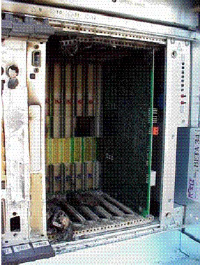
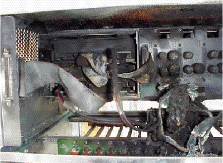
Fire resistance and containment
Telephone companies in general are highly tuned to the dangers of Central Office fires, given the well-documented incidents of Central Office fires affecting operations over the past couple of decades. Strict NEBS criteria exist for measuring fire resistance in both frame level (i.e.: equipment over 36-in in height) and shelf level equipment. For example, during fire spread testing for frame level equipment, "fire should not spread beyond the confines of the equipment assembly being tested." This includes no "visible burning of any exterior surface" and no "visible flames extending beyond the confines of the equipment being tested for 30 seconds or more."
Meanwhile, the fire propagation hazard of a unit is measured by recording its rate of heat release, which "should exceed 150 kW at any time during the test" while the average rate over 30 minutes of testing "should not exceed 100 kW." Fire propagation hazard requirements are even more stringent for shelf level units where "peak rate of heat release measured should not exceed 50 kW at any time" and "the average rate of heat release should not exceed 35 kW during any 15-minutes period during the test."
NEBS fire test methods are carefully laid out and are designed to allow testers to measure and report on:
- Fire endurance — how long it takes something to catch fire and whether the flames go out when the fire source is removed
- Fire spread — how slowly or quickly the fire spreads
- Heat release
- Smoke generation
- Gas generation
- Smoke generation
The fire spread test, for example, specifies the use of a programmable methane line burner that is inserted into the unit under test "where it is anticipated that firespread is most likely to occur." Radiometers and thermocouples are specifically placed above and around the unit. If the unit under test has internal cooling fans, they are turned on. The burner is then ignited and the flow of gas to the burner is gradually increased over 80 seconds and then decreased. Measurements are then made to see if the resulting fire is "self-sustaining." Smoke, gas and heat release is measured throughout the test.
All fires need fuel. Along with setting fire resistance and containment parameters, NEBS also presents criteria on the use of fire-resistant materials, components, wiring and cables. For example, circuit boards and backplanes "shall have an oxygen index of 28% or greater" while wire and cable need to comply to a variety of UL, IEEE and CSA standards, depending on where and how they are run.
Return to Table of Contents
Earthquakes and vibration
Next to fire and heat, vibration is a major source of equipment failure. The fact that telephone company Central Offices in Los Angeles and San Francisco continued to function during and after the Northridge and Loma Prieta earthquakes is a testament to the effectiveness of NEBS.
NEBS Level 3 criteria addresses several types of vibration, from dramatic earthquakes to office vibration to transportation vibration. NEBS assesses earthquake risk by geographic "zone." Zone 4 (at risk of Richter 7.0 or higher temblors) areas, such as the California coast, represents the highest risk while Zone 0 areas, such as Florida, are considered free from risk. According to GR-63, equipment used "in earthquake risk Zones 1 through 4 shall be tested to determine the equipment's ability to withstand earth-quakes." More importantly, this includes meeting both "physical and functional performance requirements."
During NEBS waveform testing for earthquake resistance, frame level units are tested to see that they conform to the requirement that "the maximum single-amplitude deflection at the top of the framework, relative to the base, does not exceed 3 inches (75mm)." Further, permanent structural or mechanical damage of shelves, framework and fastening hardware "constitutes a test failure." Shelf level units are let off a bit easier— permanent damage may not result in a failure, "but may invalidate the test." As for functional performance, GR-63 states that during waveform testing, "the equipment shall sustain operation without replacement of components, manual rebooting, or human intervention." In other words, as it relates to embedded computing equipment, buyers need to know that their critical hardware components will be in place and functioning to support auto-reboot and continuous operations.
How severe the earthquake test is depends on whether the equipment will be installed in a Zone 4 area, Zone 3 area, and so on. While perhaps not as dramatic as the fire tests, the earthquake test has an excitement all its own. Earthquake behavior is simulated by a waveform test, administered by means of a precisely specified shake table that shakes the equipment in three different axes. The tests need to be videotaped in such a way that "the motion of the top of the framework relative to its base" can be easily observed. Static pull tests may also be administered.
Office and transportation vibration resistance characteristics are also spelled out, along with associated tests using a shake or vibration machine. Construction, trains or traffic can all cause office vibrations and equipment needs to sustain operation in the face of such vibrations just as it needs to withstand earthquakes—i.e.: "without replacement of components, manual rebooting, or human intervention."
Return to Table of Contents
Contaminants — trouble in the air
Central Office equipment can be exposed to a wide range of airborne contaminants, both from outside and from inside the facility. Corrosive gases, for example, can be released from other equipment during a fire, while particulates such as hygroscopic dust and water-soluble salts are a significant threat in many geographic environments.
NEBS criteria states that "equipment intended for installation in controlled environmental space operate reliably for its intended life" within certain average yearly levels of contamination. These levels have been worked out for course and fine particles and for various gases such as sulfur dioxide, hydrogen sulfide, ammonia and so on. Complex tests are prescribed to determine a unit's ability to withstand exposure to corrosive gases (accelerated atmosphere corrosion tasting) and hygroscopic dust.
Return to Table of Contents
Understanding NEBS requirements for electromagnetic compatibility
Like all telecommunications equipment, embedded computer systems in a telecommunications network are susceptible to electromagnetic interference (EMI), electrostatic discharge (ESD), power faults, damage from lightning strikes, and so on. NEBS takes all these electromagnetic compatibility and safety issues into account. Electromagnetic compatibility is, of course, a complex subject and it is not a simple task to comply with NEBS ESD, EMI, and grounding criteria.
Return to Table of Contents
Electrostatic discharge
Noting that electrostatic discharges can cause device damage, alter software and firmware, and affect data, NEBS outlines criteria for immunity to ESD during normal operation, installation, and repair. Testing for ESD immunity involves using either contact discharge or air discharge methods. For example, during normal operations, a unit must show that its test points (including panels, doors, consoles, keypads, indicator LEDs, fuses, switches, sockets, etc.) can withstand 40 air discharges (15 kV) or 20 contact discharges (8 kV). During the test, according to GR-1089, "service-affecting responses, unless within system operating limits, and manual intervention shall not occur."
Return to Table of Contents
Electromagnetic interference
Equipment is also tested to see how well it avoids interference with nearby equipment. For example, radiated electronic emissions from a unit with closed doors must not exceed certain specified field strengths. A similar test is then performed with doors open. Magnetic emissions are similarly proscribed, as are conducted emissions (AC and DC power and signal leads) from the unit into public utility power lines.
Return to Table of Contents
Jolts from the blue — lightning and AC power faults
While ESD and EMI represent the commonplace, everyday side of electromagnetic compatibility, power faults and lightning surges represent the dramatic and (thankfully) occasional side. The arbitrariness of these occurrences dictate two levels of criteria. First level compliance holds that the equipment be undamaged and able to continue operations after the fault or strike. Second level criteria state that the unit "may sustain damage, but shall not become a fire, fragmentation or electrical safety hazard." Tests include short circuit (tip to ring, tip to ground, etc.) and surge tests (using a lightning surge generator) on at least three units. Additional lightning surge tests exist for units that will operate by commercial AC power.
Return to Table of Contents
Contributed by Force Computers, a Solectron Company, 5799 Fontanoso Way, San Jose, CA 95138-1015. Tel: 408-369-6000; Fax: 408-371-3992.